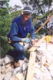
Dan doing some of the initial stages of formwork.
(Click on the image to see a larger version of this picture, and then use your browser's back button to return to this page.)
What is "Formwork"?
Formwork is the wooden structure which is used to hold the concrete in
place as it is poured. In this instance, because the foundation is not
level but varies as much as 18 feet, the formwork has many steps to compensate
for the changes in height. The minimum concrete depth allowed is 8",
but in a setting like this it varies from 8" to about 6 feet along the
walls. Before any of this is started the exact corner locations must be
accurately known and this was done when the site was surveyed. The wooden
structure was started May 27 and completed on June 22, 2000.
Formwork

Dan doing some of the initial stages of formwork.
(Click on the image to see a larger version of this picture, and
then use your browser's back button to return to this page.)
Using a string between the corner marks as a guide, the first step is to drill the rock and then bond in the rebar using an epoxy cement. The next step is to cement in some threaded rod which will be used to hold one wall of the formwork in place. A length of 2 X 4 lumber is then drilled at the appropriate spots and bolted down to the rock face using the threaded rod, ensuring that the board is level from side to side. This is made as level as possible as this forms the base of the wall edge. Clearly many wedges are required to achieve this.
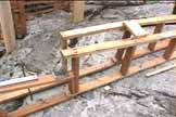
The form work is then built up to the required heights.
The photo above shows how the formwork is assembled. The horizontal on the rock nearest the viewer is the one which was set initially. After this "shiplap" is used in vertical pieces to act as a mould for the concrete. Shiplap is used as it will easily break along the grain and this can simplify removal after the concrete is poured. The bottom of the shiplap is shaped to the approximate contour of the rock face to prevent the concrete from flowing out. The photo below shows the shiplap in place. One side of the form will be cut horizontally and will be the upper edge of the poured concrete. The two sides are kept a constant distance apart by the use of snap ties (a flat length of steel with three nail holes at each end which are nailed securely to the formwork. They are snapped off when the form work is completed.) Finally, 10" long, 5/8" diameter, galvanized bolts are attached vertically such that they will stick up 3" above the concrete. These are used to attach the first level of lumber supporting the house to the concrete walls. The epoxy for the rebar, and the bolts all form part of the earthquake protection which is a requirement of the British Columbia Building Code.
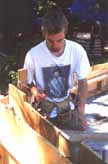
Mike is getting ready to cut one side of the formwork level at the desired concrete height.
The next photo shows a particularly challenging section of the outer wall. It is obvious that a considerable height variation is being managed! The steps where the cement will change height are clearly visible. Snap ties were also used to support the bulkheads in place at each height change, although by leaving a length of 2 X 4 extending beyond these, a length of 2 X 4 could also have been used. As the wall thickness is designed to be 6 inches, a 1/2 inch section of plywood is also inserted at each bulkhead as 2 X 6 lumber is actually only 5 1/2 inches wide. It can readily be seen that formwork is a major task!
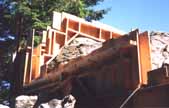
A particularly challenging length of formwork.
Fireplace
Stephen and Marja will have a special Finish stone fireplace to heat their house. This requires structural considerations at this stage and a concrete support "T" shaped section was constructed. Much of the basic construction technique was similar to that used for the walls, however, as the structure is 8 feet tall considerable reinforcement was included as well as bracing to ensure the structure stays in place as the concrete is poured. The basement of the house will be the area below the level of the fireplace. Clearly not all the basement is useable as it will vary in height from about 8 feet down to a few inches in some parts. There will be enough space to allow a workshop - an essential for Stephen!
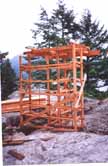
The start of the formwork for the fireplace support structure.
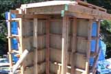
The completed fireplace formwork.
The blue plastic shown in the picture above is the covering for some of the cement now brought to the actual building site. Two vertical sections of shiplap were not fastened at this point to allow the formwork to be cleaned out before the concrete was poured. At the top of the structure formwork is included to provide a 6" slab of concrete.
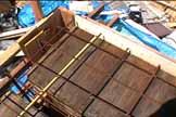
The formwork for the 6" slab to form the base of the fireplace.
Deck
Due to the fact it is the north side of the building site which has a section 18 feet below the southeast corner, Stephen decided to put in a 5" deck here to support one section of the house. This allows shorter lengths of lumber to be used above it, which will decrease the expansion and contraction. The deck is supported by two pillars along one edge and is attached to the rock along the other edge and at both ends. A considerable amount of reinforcement is used in this section as it will take part of the weight of the house. Where the deck is unsupported a 6"wide, 14" high concrete beam is included in the formwork.
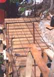
The formwork for the deck takes shape.
When the concrete is poured this formwork will have to carry a lot of weight. To support this 6" beams were used supported by a bar attached to the rock face, and by verticals resting against the rock base. The photo below shows the support structure underneath the deck. It also shows one of the pillars which use coated cardboard tubes (called "sonotubes") to support the concrete when it is poured.
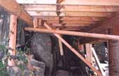
The support framework for the deck formwork.
The final photo of this sequence shows all the rebar in place for the deck. There is a lot used here! The pillars both have four vertical 15mm rebar rods which are tied together at frequent intervals with 18 gauge wire.
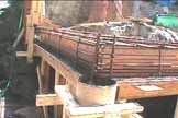
The rebar is finally in place for the deck.
Return to Passage Island Site Development History Page. or to Passage Island Lot #9 Home Page. or to Site Index Page.