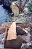
Formwork for the concrete supports of the hoist at the lower end.
(Click on the image to see a larger version of this picture, and then use your browser's back button to return to this page.)
Design Criteria for the Hoist
Once the decision was made not to use a helicopter to transport materials (see winch page), the question of load to be
carried was addressed. It was decided to design the hoist for 1,000 lbs (450kg)
with a safety factor of at least 4:1. A route was chosen from the beach to the
building site that would damage the minimum of plant life. Basically the design
would use two A-frame structures, one over the beach area, the other at the top
of the slope to the site. From the beach area a cliff rises about 20 feet (6m)
to a level area. From there it rises steadily the balance of the 60 feet (18m).
Supports for the A-frames were required at both the top and the bottom of the
hoist route. These were constructed of re-enforced concrete.

Formwork for the concrete supports of the hoist at the lower end.
(Click on the image to see a larger version of this picture, and
then use your browser's back button to return to this page.)
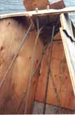
Detail of the formwork for the lower right hoist support.
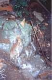
Detail of an upper hoist support. Note the rebar bonded into the vertical rock face.
The next photo shows Stephen with the cables for the hoist. One of the A-frames is behind him. The green tarp just visible on the right of the picture shows the housing of the electrical supply. This includes the 3KW generator and the batteries. The main wire supporting the hoist load is 1/2" (1.25 cm) galvanized wire with a breaking strength of greater than 20,000 lbs (9,100 kg). The smaller wire used to pull the load up is 1/4" (0.63 cm) galvanized wire with a breaking strength of greater than 4,000 lbs (1,800 kg).
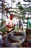
Stephen with the wire for the hoist.
The A-frame consists of two 18 foot (5.5 m), 4" (10 cm) diameter galvanized steel poles. These are bolted to the concrete support poles at the bottom and to each other at the top.
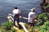
Stefan and Stephen placing one arm of the A-frame in position.
The next photo shows the landscape between the beach and the first level area where the A-frame is mounted. This photo was taken before any of the guy wires which support the overall structure were added. The upper poles are supported by a block and tackle arrangement at this point in time. For this vertical section there is a 3:1 pulley arrangement as this section is a straight lift.
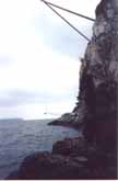
View of the rock face from the beach to the first level area.
The following two photos show the guy wires being added at the lower end. The rock is first drilled and then threaded rod is epoxied into place. The guy wires are the same as used on utility poles - 7/16" (1.1 cm), 7 strands of galvanized wire. Three guy wires pass through the top of each A-frame and are secured to the rock. In the second photo below Stephen is adding the third guy wire. He has pulled himself up using a block and tackle, but also has a safety line secured by Dan from above.
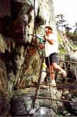
Stephen drilling the rock. Yes, he can get electric power down to the beach.
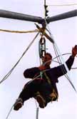
Stephen waving (actually fixing 3rd guy wire) from the top of the lower A-frame. He is over the ocean at this point!
From the first cliff the ground slopes upwards relatively evenly for much of the way to the top. The next photo shows the contour of the land in this area with the main hoist wire clearly visible.
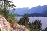
Hoist wire with Coastal Mountains in the background.
The next photo on this page shows a load of concrete coming up from the beach. Here a palette is used as the base, and this is supported by two lengths of rope secured at the outside corners of the palette to a hook on the hoist. This hook is actually the lower pulley of a 3:1 pulley system. The upper carrying system consists of two pulleys running over the main cable. The carrying system prevents the device from coming off the cable. The winch cable is attached to the lower pulley which is then pulled up to the carrier when the load is at the top of the section from the beach to the top of that cliff. When the carrier reaches the top of the run a large hook picks up one of the carrier bolts. This prevents the load from then rolling down the cable when the load is lowered to the ground. Any device carrying this amount of weight requires a great deal of caution.
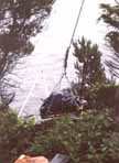
A load of concrete nears the top of the run. The concrete is protected from the rain by the plastic cover!
The main carrier for the load and the main hoist pulley are detailed below. The carrier has two wheels under the main cable and two under the winch cable. It is designed such that it is impossible for the carrier to come off the main cable.
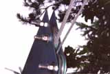
Notice the heavy grooving of the pulleys in the winch carrier. There is a lot of pressure on the main cable!

The hoist pulley gives a 3:1 advantage. (One end of the cable is attached to this block.).
Go to page giving information on the winch.
Return to Passage Island Site Development History Page. or to Passage Island Lot #9 Home Page. or to Site Index Page.